|
Creating a Design For Laser Cutting
Goals
We will cover the main things that need to be taken into account when designing for laser cutting. From what type of file format and software are appropriate for design as well as general settings and design techniques.
Content in a nutshell
- It is possible to work with a multitude of file types and software for producing a design for laser cutting including vector and raster types. Both can be processed but raster images can be used for engraving only, while vector graphics can be used for both engraving and cutting.
- In order to cut, the laser cutting head requires a vector path it can follow. Only vector graphics with the smallest possible line thickness or 'hairline' width will be cut by the laser. All other graphics, like solid shapes or lines thicker than 0.01mm, won't be cut. The software will automatically convert them into a raster format, which can be exclusively engraved.
- When engraving with a laser one can distinguish between vector and raster engraving. Vector engraving is essentially the same as vector cutting with the only difference being the lower power setting, so as not to cut all the way through the material. For raster engraving, the input file can either be a vector file or a raster image.
Vector vs Raster
When working with laser cutters it is important to know the difference between using vector and raster images.
A vector file format stores all the lines and shapes as Mathematical formulas, which makes them infinitely scalable. Raster images, on the other hand, are pixel-based. This means that they consist of pixels that are squares of a certain color value. Vector images can be scaled up without any loss in quality whereas raster images will start to “pixelate” at a certain enlargement. You can read more about the difference between them here.
Both image file types can be processed but raster images can only be used for engraving and not for cutting, while vector graphics can be used for both.
Design for Vector Cutting
[Image courtesy of Ponoko]
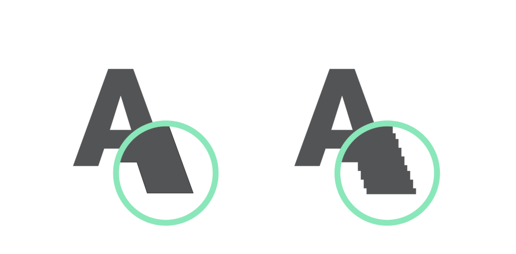
In order to cut, the laser cutting head requires a vector path it can follow. Only vector graphics with the smallest possible line thickness or 'hairline' width will be cut by the laser. All other graphics, like solid shapes or lines thicker than 0.01mm, won't be cut. The software will automatically convert them into a raster format, which can be exclusively engraved.
While designing for cutting, one always has to be mindful of the kerf. This varies from material to material and is also dependent on the specific settings of the laser. For many materials, the kerf will be somewhere between 0.05 mm and 0.5 mm. The size depends on the characteristics and thickness of the material you're cutting, which will give some limitations to your design. Fine details concentrated in a smaller area would mean that the laser would dwell in the same place for a prolonged period of time. This would create a lot of concentrated heat and might cause the material to catch on fire or melt, especially if the material is flammable. A good practice is to leave at least a 3 mm gap between two parallel lines to ensure the part being cut doesn't get damaged.
Besides this, material limitations are also always present. Thinner features have a much higher tendency to break and now materials used for laser cutting, like wood or plastic, tend to be very brittle, to begin with. This has to be accounted for during design so the pieces don't snap easily after being cut.
Design for Rastering
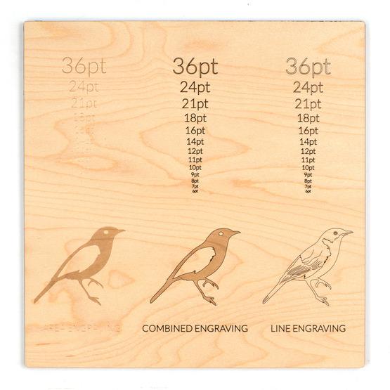
Comparison of vector and raster engraving on wood veneer [Image courtesy of Ponoko]
When engraving with a laser one can distinguish between vector and raster engraving. Vector engraving is essentially the same as vector cutting with the only difference being the lower power setting, so as not to cut all the way through the material.
For raster engraving, the input file can either be a vector file or a raster image. As we mentioned earlier, if the line-weight exceeds the 'hairline' value, the image will be converted to pixel data. The laser then moves across the image, pixel by pixel, much like an inkjet printer. Instead of shooting down a pulsing beam, it creates fine dots at a selected DPI (dots per inch) that directly correlate to the image resolution and affects how fine an image appears. The higher the resolution of the image, the denser the grid of points that the laser will travel over and the Darker the image will be. This can be compensated with a higher speed or a lower power setting, depending on the desired effect. Photos would need to be converted into Grayscale before they are to be engraved.
Design Software
There are a number of suitable file formats that can be used for laser cutting. Below you can find a brief list of possible options as well as software that you can use to process and export them;
Vector file types: SVG, EPS, PDF, DXF, DWG, CDR (CorelDRAW), AI (Adobe Illustrator)
Raster file types: JPG, PNG, GIF
2D Design:
- Inkscape (free, open-source)
- QCAD (free, open-source)
- CorelDRAW
- Adobe Illustrator
- AutoCAD
3D Design:
- Autodesk Fusion 360 (free for hobbyists and small businesses)
- Blender (free, open-source)
- FreeCAD (free open-source)
- Sketchup
- Tinkercad (free)
- Solidworks
- Onshape
- Rhino
General Settings
The very first thing you should consider in your design is the maximum dimensions of the laser-cutting bed.
These measurements will define the maximum size of the pieces you will be able to cut. If for any reason these might exceed the table, such as when making a large topography model, consider splitting the design into smaller segments and account for the joints between them.
Colour Mapping
The color mode in your file should be set to RGB.
Different colors are usually used to specify different processes. For example, red could be used for all the parts that will be cut, and black will be used for engraving. You can use multiple different colors in your cutting process that each has their own respective settings, but it is in most cases better to do each type of treatment separately. For example, you can have a design where you would like to cut out a design and engrave it. In this case, think of the order that you would like the processes to take place, so as not to diminish the quality of the final outcome. If the pieces were cut out first and then engraved, they might move on the laser cutting bed and the engraving could be potentially off-center in some cases.
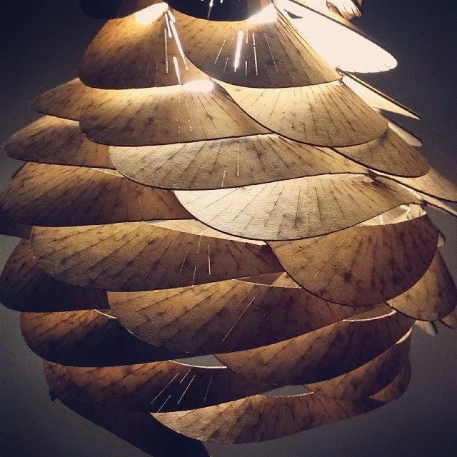
Stacking / Layering
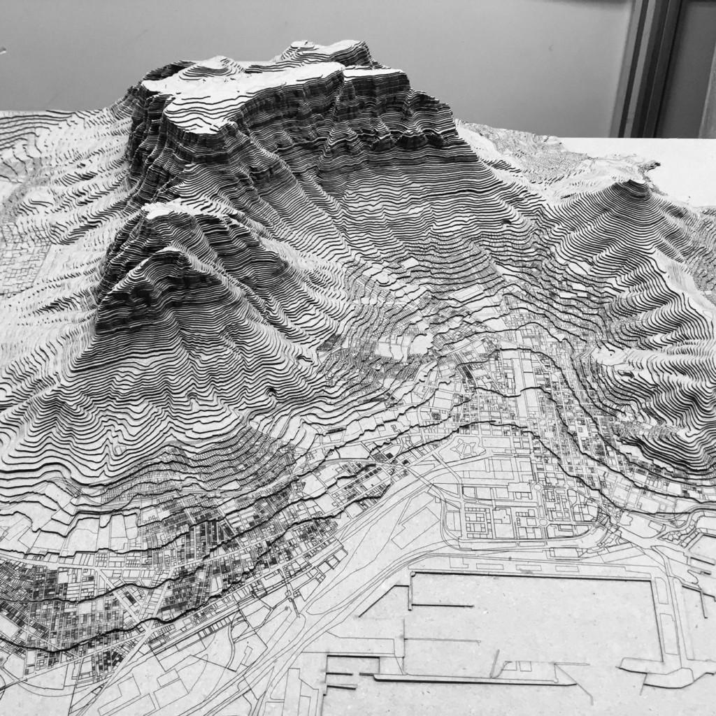
Example of a topography made from contour layers in cardboard. [Image courtesy of Thomas Pavitte from pinimg.com]
Stacking layers is one of the most basic types of assemblies of laser-cut parts. Usually, it would be a good technique on how to represent a natural or built topography, as well as any other massive structure.
Many 3D software, like Autodesk Fusion 360 or Rhino have integrated slicing functions that can help you produce the contour lines of the form you want to construct. When designing your own pieces, make sure to label them for easier assembly.
If you're interested in how to practically achieve this in Rhino, you can find a useful workflow here:
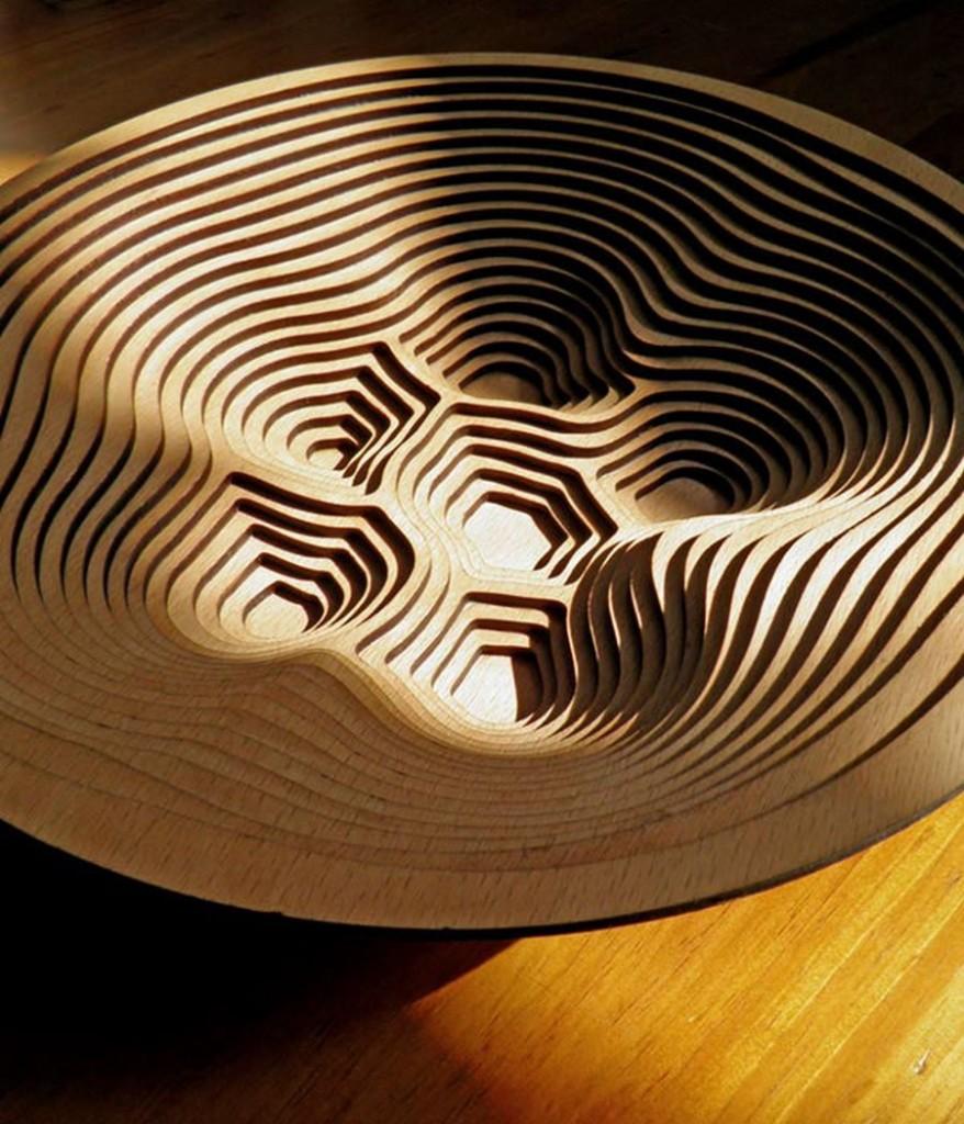
Example of a bowl created with layering laser-cut plywood pieces. [Image courtesy of Thomas Pavitte from Parametric house]
Working With Joints
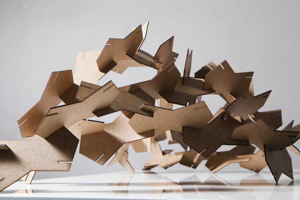
Example of an assembly using rigid joinery using thin pieces of MDF. [Image courtesy of reSITE 2013]
Despite being able to produce only flat pieces with a laser cutter, there are numerous ways of making joints that even carry over from other trades like woodworking and metalworking. Whether you choose to use simple friction-based joints or screws and bolts, always be mindful of the material kerf when designing the pieces. This will depend on the material you choose and its' thickness, so always make initial experiments before proceeding to cut the entire design.
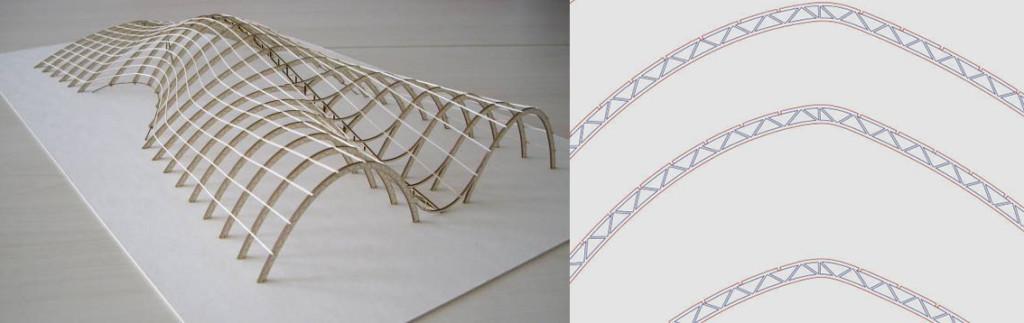
Perpendicular laser-cut trusses are connected via thin longitudinal elements that fit into predesigned grooves. [Images courtesy of Matteo Fraschini]
Kerf Bending or Living Hinges

Example of an flexible glove achieved through kerf bending of plywood. [Image courtesy of Renee Verhoeven]
Although most materials that can be cut in a laser cutter are pretty brittle, it is possible to change that with a bit of design. By cutting out certain sections in a specific pattern, we can alter the characteristics of a normally rigid material to make it more flexible. These bending parts are called kerf bends or living hinges. When we create cuts or notches in a material at specific points, they relieve inner tension, redirecting forces and allowing it to bend. This can be used to create flexible hinge joints or even snap-fit hinges that keep parts locked together.
You can find more information on the subject and some inspirational content here:
Instructables: Curved Laser-Bent Wood
Instructables: Laser Cut Bloom Lamp