2D CAD DRAFTING
2D drafting drawings and hand-making models used to be the only method to design and present a building. After computational tools being introduced to the architecture field, the drawing becomes easy. The essential of 2D drafting is to transit 3D into informative and accessible pictures to build a communication bridge between the architect, the client, and the construction party.
Traditionally, all drawings have a scale on paper, which is a ratio of distances measured on paper to distances in real life. Digital drawings are still mostly printed on paper in some conventual scale in order to be used on construction site.
It is important to note that in a digital workflow, drawings don’t have a defined scale before they are printed on paper and one would usually work in the “real scale” or 1:1 with real distances. So “scaling” is an issue still mostly related to traditional drafting workflows and relates to limitations of representing large objects on papers of compact size.
If we could draw our building on paper of the size of the building, we would not have to worry about the scale at all, but this is not very practical. It is important to note that only drawings made with parallel projections have an easy-to-read scale. This is not true for drawings in perspective, which is why they are mostly used for visualization, not for producing construction plans.
The basic of 2D drafting by computational tools is vector. Please refer to Vector Chapters.
The 3D model tool enables some drawings to be completed without 2D drafting, such as perspective drawings which can be rendered directly in the 3D model. However, there are still many pictures that 2D drafting could create, such as the following ones:
Drawing 2D
These pictures express information completely flatly. They can be regarded as orthographic projection or sectioning. Usually, construction drawings are made in this way.
- Projection: masterplan and elevation
- Sectioning: plan, section and detail drawing
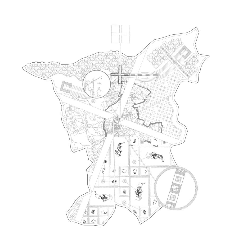
Master plan. Source from "The workers city of Motovun", student work from Re: public Motovun workshop from 2014.
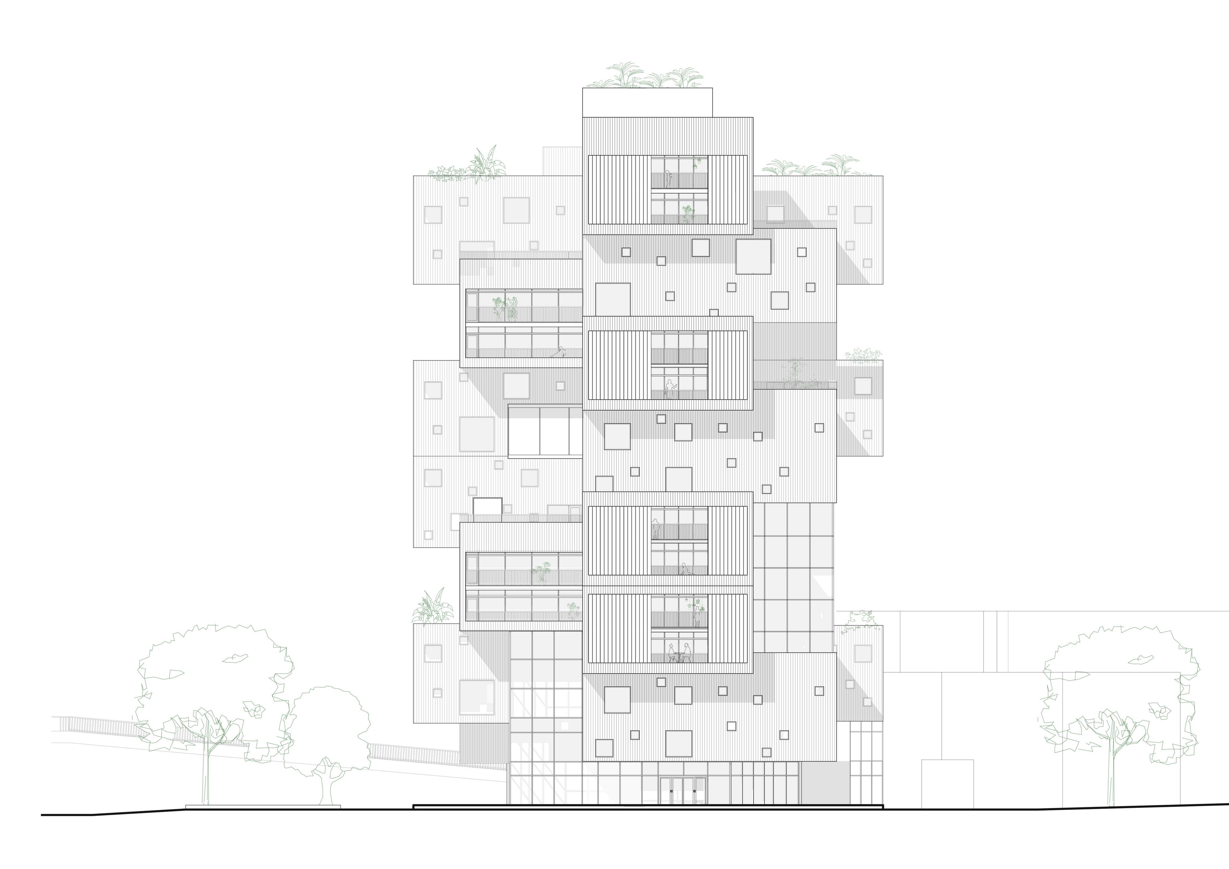
Elevation: Fanyi Jin
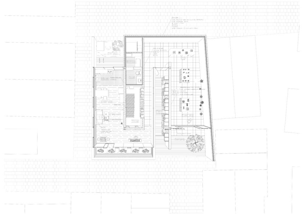
Ground floor plan: Fanyi Jin
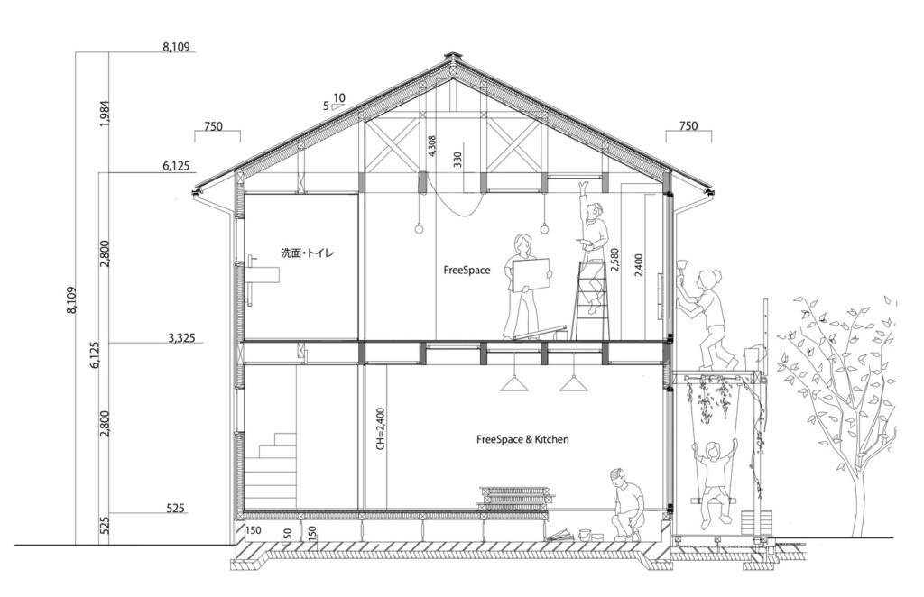
Section. Source from Archdaily: Frame house
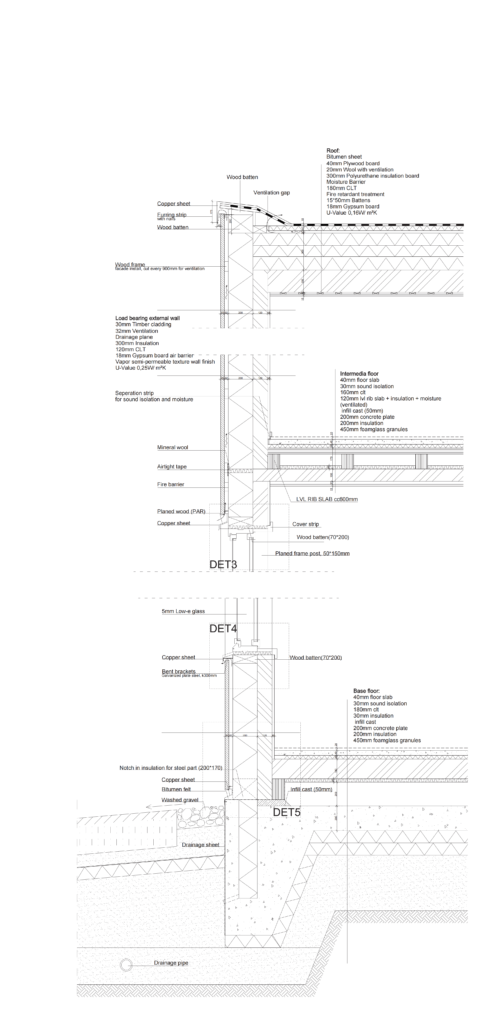
Detail drawing: Fanyi Jin
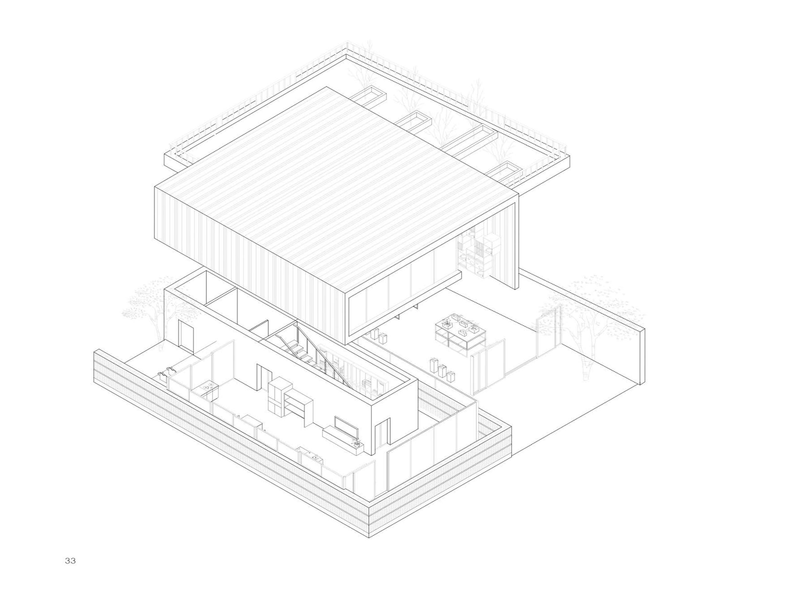
Drawing 3D
These pictures contain 3D information. They look like captures in 3D model. But unlike perspective drawing which only shows a general expectation of the building, they express accurate dimensions.
They are axonometry and perspective section. Once we know the basic rules, we can produce more specific drawings such as 3D detail drawings.
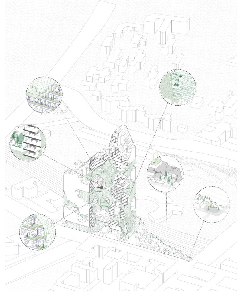
Axonometry: Fanyi Jin, Tuuli Töniste, Maral Alaei.
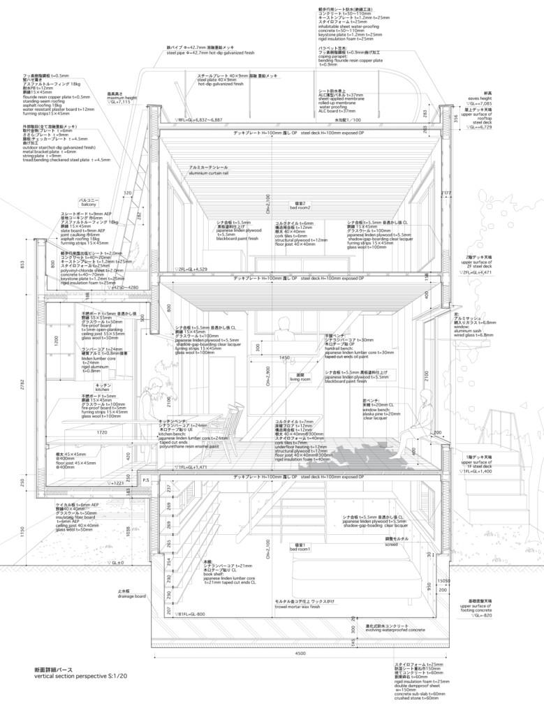
Perspective detailed section download from Extra extra Magazine/Talk/Atelier Bow-Wow. Source from: Graphic anatomy by Atelier Bow-Wow.
3D details: Stephane De Weck(ETH)
Other cases: such as accurate 2D draft that prepare for 3D modeling, and some analysis.
The 2D draft made for 3D model is usually some simplified plans, sections and elevations. Everyone has their unique modeling habit, thus no more unified description will be clarified here.
The pictures below are examples of steps of a building block axonometry construction starting from a simple floor plan drawing using rules of descriptive geometry.
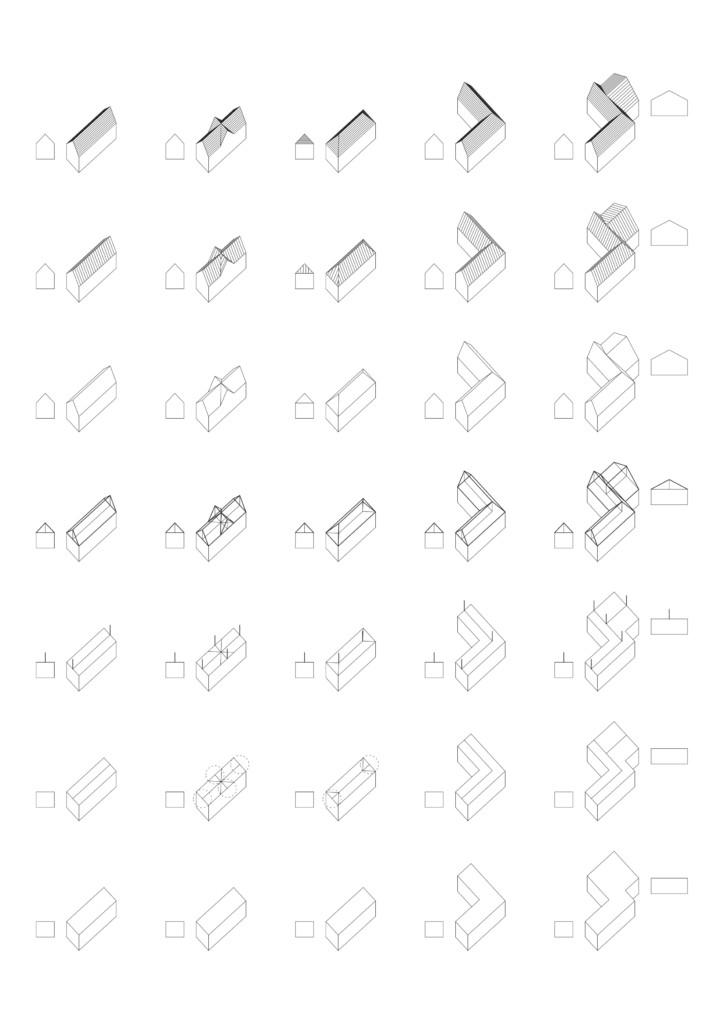
Source ARK-C0011 - Basics: Digital Storytelling, PIcture: Luka Piskorec, 2020
In general, in these cases the drawing are recommended to be produced by 2D: 1) requires accuracy; 2) a series of pictures with uniform style; 3) initial quick drafting; 4) special analysis.
The following chapters will explain these pictures in detail. Enjoy!