|
Drawing 2D: Projection and Section
Goals
2D architectural drawings (plan, section, elevation, and masterplan) are the most basic architectural drawings. They are the primary for construction drawings (2D), and they are also a pre-step required before drawing the building into 3D.
Content in a nutshell
- The viewing lines are all parallel in 2D architectural drawings.
- Plans and sections are section drawings.
- Elevations and master plans are projection drawings (no section cutting lines).
What is 2D architectural drawing
Architectural drawings are essentially two-dimensional projections or sections of three-dimensional objects. All of these are parallel views, meaning that the viewing lines are all parallel. This makes it easier to construct them and measure distances between various elements in the drawing.
Projection: Most common projections are elevations and master plans. Elevations are just views from outside which show facades of the building; Masterplan is the top view of a large range of buildings and the environment.
Section: Plans are in fact horizontal sections of a building with the view towards the floor. Sections are in general vertical sections of the building which show relationships between different floors. there are usually four of them.
Additionally, to these, other projections like for example axonometry show the building from different angles.
Section drawings
Plan
- The horizontal section of a plan is usually 1.2 m above the floor surface.
- Draw axis and columns (if there are any).
- Draw centerlines of walls.
- Recognize which lines are cutting line and which lines are viewing line. Then offset the centerline according to the thickness of the wall. Cutting lines are thicker than viewing lines.
- Add windows. The wall line of the cut window is the viewing line, and the glass line is the section line. There are several methods of drawing the window. The window higher than the section surface could be marked by dashed lines.
- Add furniture and stairs.
- Add text and height marks.
Picture: Fanyi Jin
Section
- Draw the section cutting line on the plan, and rotate the plan to the direction that matches the section. Note the direction of section mark: The section mark is generally composed of one long line and one smaller line, they are mirrored to both sides of the building plan. The longer line indicates the position of the cutting plane, the shorter line shows the direction of observation.
- Add the reference lines according to the plan.
- Draw centerlines of walls and floors.
- Recognize which lines are cutting lines and which are viewing lines, then offset them.
- Add windows, furniture and stairs.
- Add text and height marks, the style of the height marks is the same as elevation drawings.
Picture: Fanyi Jin
Landscape architecture point of view
For landscape architects, sections may contain more information about the environment. You should pay attention to the relationship between the site and your design when drawing sections.

Projection drawings
Elevation
Notice that we handle drawing an elevation without a 3D model.
Workflow is similar to section drawings.
- Choose the drawing facade.
- According to the plan, draw reference lines along with the turning point of the elevation.
- Mark the height line for each part of the elevation.
- Draw the overall shape of the facade, do not forget the component behind the cutout part.
- Add windows, doors, glass frames, and other details such as material texture if needed.
- Add shadow if needed.
- Mark the height on one side of the building. The elevation mark is a downward-facing triangle with height data marked on the extension line of its upper edge.
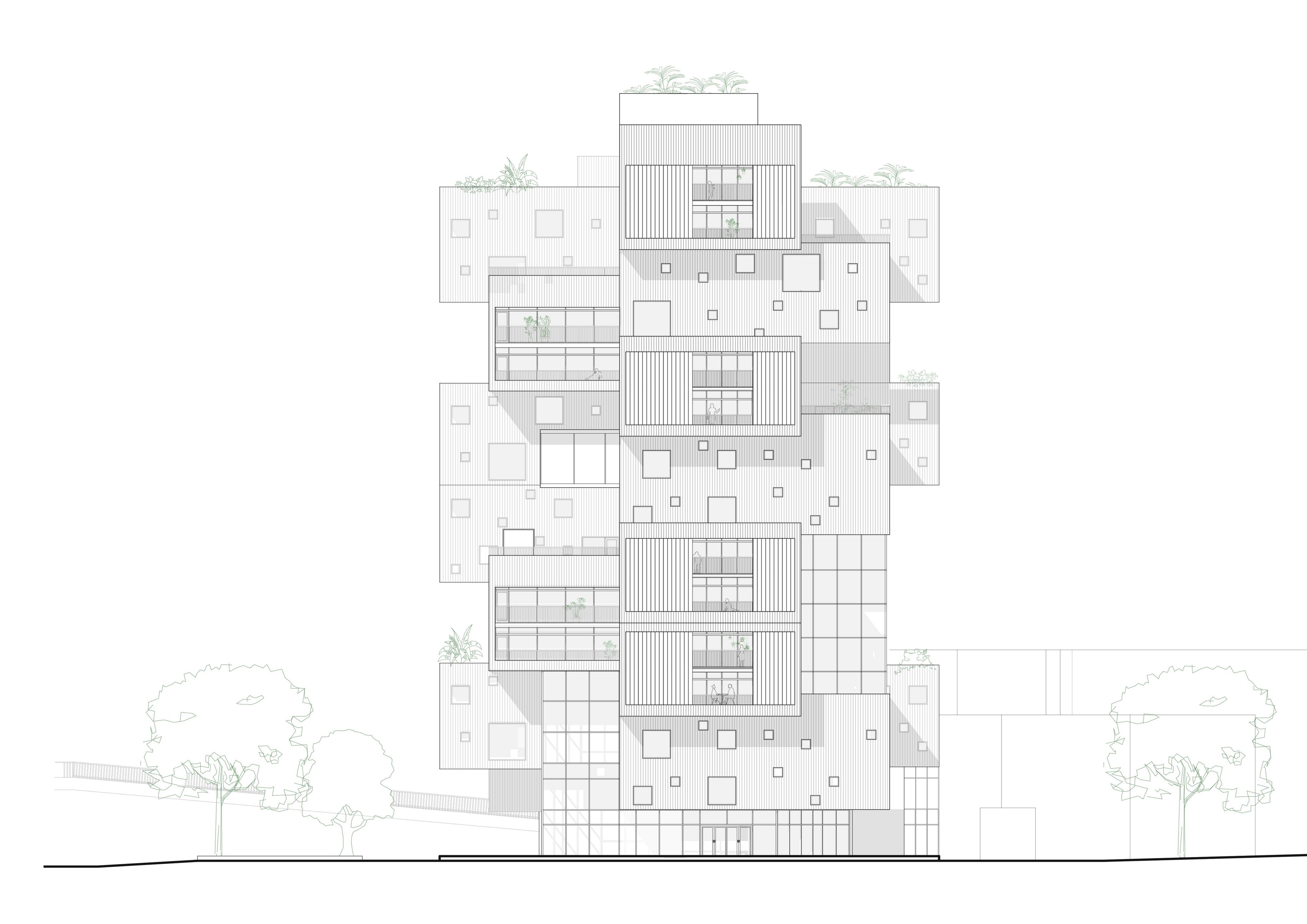
Picture: Fanyi Jin
Master plan
- Choose drawing range.
- Add map building outlines, roads, contours, trees, and other needed details. The detailed content of the drawing depends on the purpose of the drawing. Construction drawing requires very detailed information, while other drawings may only emphasize the important information for the design. Masterplans of some cities are public resources (such as Helsinki map) that could be download online.
- Mark the project. There are many ways to address your building (or area), such as shade the roof, add shadow to the designed area, draw the outline of the building, etc.
- Add additional information, such as compass, scale, material mark, text, etc. Additional information also depends on the purpose of the drawing. Sometimes the master plan is combined with the overall description. The most important thing is to determine what the drawing wants to express.
Three different types of master plans.
Top left: Town plan of part of Tapiola. This master plan shows the official information about the area. Downloaded from Kartta Espoo;
Top right: Masterplan of De Lemos restaurant. This master plan shows the relationship between the site and the building, emphasizes the building shape and terrain condition. Picture from Archdaily: De Lemos
Lowest: Masterplan of Gränsland area. This master plan shows the overall design of an area instead of a single building. Picture from Blank architects: Gränsland
Urban design and landscape architecture point of view
For urban design and landscape design, the masterplan usually has a much larger scale than the site plan for a single building. The larger the scale is, the less the details will be displayed. In that case, you must be very clear about what is the most important information. Add color and texture if needed.