|
The Basic Features of Rendering: Material
Goals
This chapter introduces the basic material parameters, which are similar in many rendering software. By adjusting the mentioned parameters most real world materials needed in design and architecture can be created. Content is simplified in places in order to make it more beginner-friendly.
Content in a nutshell
Materials can be divided into metals and nonmetals. Rough surfaces are matte but smooth surfaces have clear reflections instead. Images can be applied to materials to give 3D objects texture.
Metallic and nonmetallic materials
Different rendering engines have different setting for materials. With the gained popularity of the physically based rendering (PBR) workflow the basic choice when creating a material is whether the material is a metal or a nonmetal.
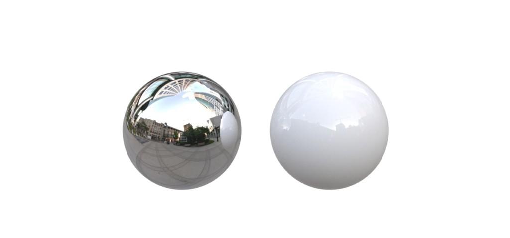
Metallic material and a nonmetallic material. This and other pictures in this page: Anssi Ahonen
Color & Texture
Another basic parameter for a material is it’s diffuse/base color. Choosing color appears straightforward but the final outcome depends on other material parameters, lighting, environment and the software used.
If the material has many colors (e.g. print on a canvas, wood), an image/photo can be used as a texture. Texture maps can also simulate multiple materials at once (e.g. brick wall) which can save time and resources. A good texture is of high resolution and tileable.
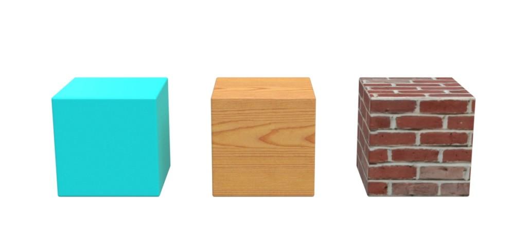
Color and a texture maps applied to objects.
Roughness
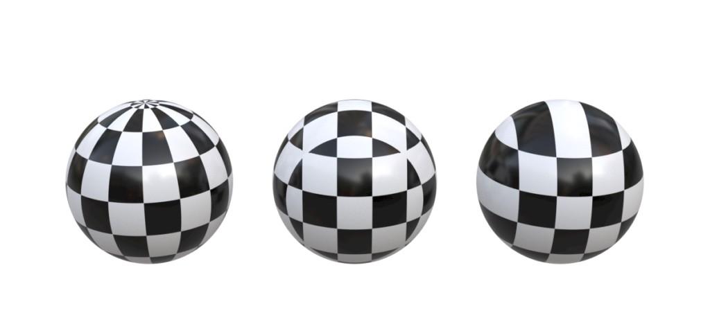
A smooth surface (material) has mirrorlike sharp reflections (light is reflected uniformly). A surface like this can be described as "glossy". Matte surfaces have microscopic scratches or granular structure that blurs the reflection (light is reflected unevenly). This kind of surface can be described as "rough".
Since microscopic surface imperfections are usually not modelled, 3D rendering software can use either the material parameter roughness or glossiness to describe this phenomenon. Most surfaces (materials) are not fully glossy or rough – they fall somewhere in between.
Note that also bumb mapping can be used to simulate roughness if the texture scale is very small. And if the roughness varies along the surface, a so-called roughness texture can be used.
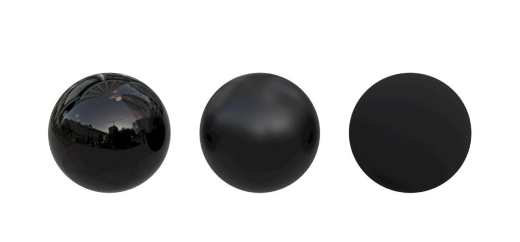
A smooth glossy surface (sharp reflections), rougher surface (visibly blurred reflections) and a rough matte surface.
Transparent objects
Different programs have different settings for creating transparent materials like glass, plastics, water etc. For example opacity and transparency distance control how the material appears. The different algorithms also produce different levels of realism – not all software simulate complex phenomenon like dispersion for example. Transparent objects also refract light and that is controlled with refraction settings (note that thicker objects bend the light more).
Sometimes in order to save time, fake (physically incorrect) materials can be used. For example, building windows can be modelled without thickness and customized material used to compensate.
Some materials are translucent – the transparency appears blurred. This is similar to roughness but can be adjusted separately for the surface and the inner material.
(Note: The transparency of an object can be controlled with a texture. This texture is called an opacity map or an alpha texture.)
Clear glass (thin and thick), fake glass (no thickness) and translucent (frosted) glass.
Bumb & Displacement maps
Many times, it is better not to manually model small surface details like bumbs & scratches. Instead, a bumb map can be used. Bumb mapping creates the illusions of depth on the surface – the surface is flat even though it looks three dimensional. This saves modeling time and is very fast to render. Bumb maps are black and white (although colored images can be uploaded), the black meaning low points and the white high (can be inverted).
Normal mapping is similar to bumb mapping but more advanced. Normal maps are easy to distinguish by their bluish base color.
Displacement maps deform the original surface and create real 3D forms. This is more taxing to the hardware so use it wisely. Bumb & displacement maps are often used together with corresponding color textures.
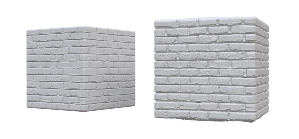
Bumb mapped cube (left, see flat surfaces) vs a cube with additional displacement map added (right).
Emissive materials
A material can be defined as emissive. This means that the material emits light to the scene (object becomes a lamp of sorts). Color can be determined as RGB or Kelvin – also textures can be used. Output can be defined in lumen, lux, watt, simple intensity multiplier etc. Emissive physical objects are many times slower to render than other type of lighting.
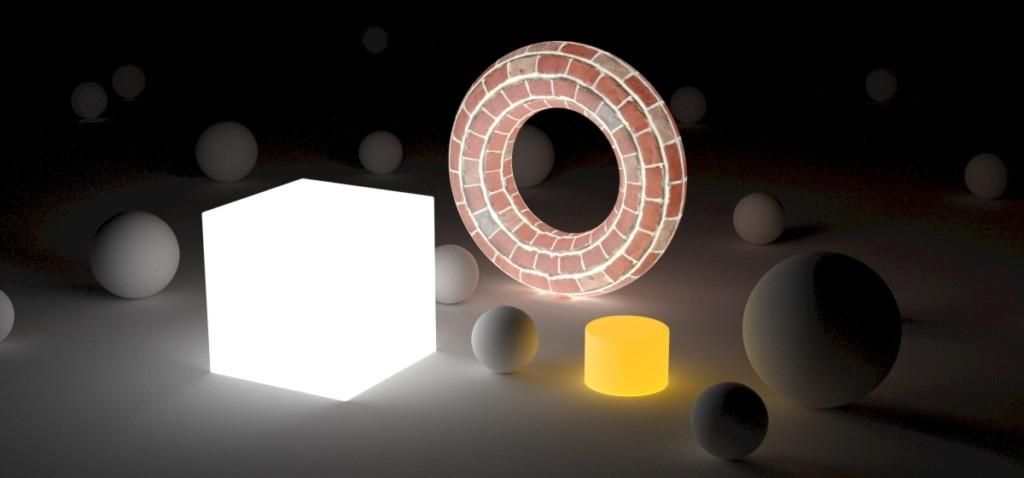
Three objects with emissive materials.
Texture mapping objects
Texturing means mapping a 2D images to 3D objects. This can be tricky – in some cases it is mathematically impossible without distortion. It also matters whether we are mapping a single surface or a polysurface object consisting of many individual joined surfaces.
Many times using box mapping is a fast and reasonably good solution. If needed a more advanced custom UV-mapping can be created. Surface coordinates are described as UV (somewhat like XY).
When texturing objects it is important to make sure the texture used is of high quality (enough resolution) and tileable (repeats seamlessly without standout repeating features) if needed.